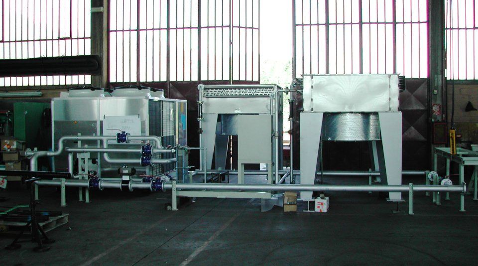
Systems
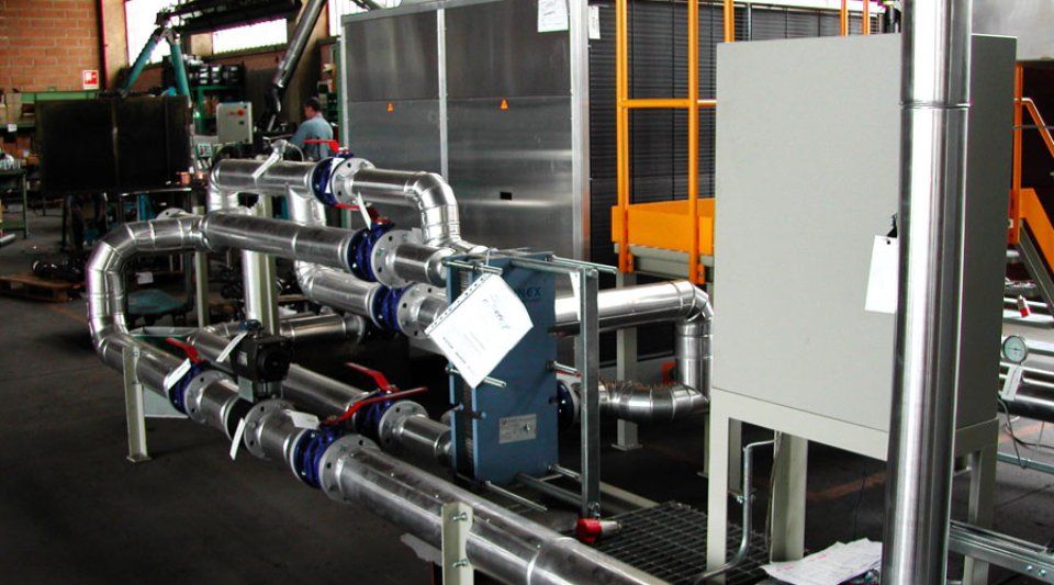
To counterbalance the chemical and physical changes that are generated inside the closed industrial systems (boilers, ovens, etc.), chemical dosing equipment is needed. This is a series of parts - tanks, injection and transfer pumps, agitators, valves, level indicators, etc. - which are managed using information supplied by our client or developed by us, and inject a certain amount substances such as ammonia, hydrazine, phosphate, etc. accordingly. At the same time, "purification" systems are also made, using similar items to those listed above, which, with the aid of special filters, purify the water entering the system according to specifications. Industrial chemical processes can be shown in various ways, for example by a simple process diagram (demonstrating the equipment and main movement of materials) or by a Piping & Instrumentation Diagram (where all the equipment and control instrumentation is highlighted). The Process Flow Diagram, or PFD or flowsheet, is a diagram commonly used in chemical and process engineering to indicate the general scheme of processes and equipment of a plant. In this sense, the process scheme turns out to be the first step in the system design, followed by the energy and mass balance to follow with the mechanical scheme. The PFD illustrates the relationships between the main equipment (or units) in which the chemical process takes place, without taking into account many details, such as the detailed structure of the piping and different ancillary equipment. The purpose of the PFD is therefore to give an idea of the process that takes place in a plant or in a section of it, without going into too much detail.
Generally a Process Flow Diagram relating to a single chemical process can contain:
- main piping lines
- main equipment
- control valves and other main valves
- connection lines with other systems
- main bypass and recirculation lines
- current and data identification useful for classification (temperature, pressure, flow rate, density, etc.)
- pipe line numbering
- control instrumentation (e.g. sensors and actuators)
- secondary bypass lines
- shutoff valves
- purge valves and drain lines
- safety valves and check valves
- flanges.
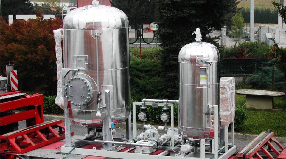
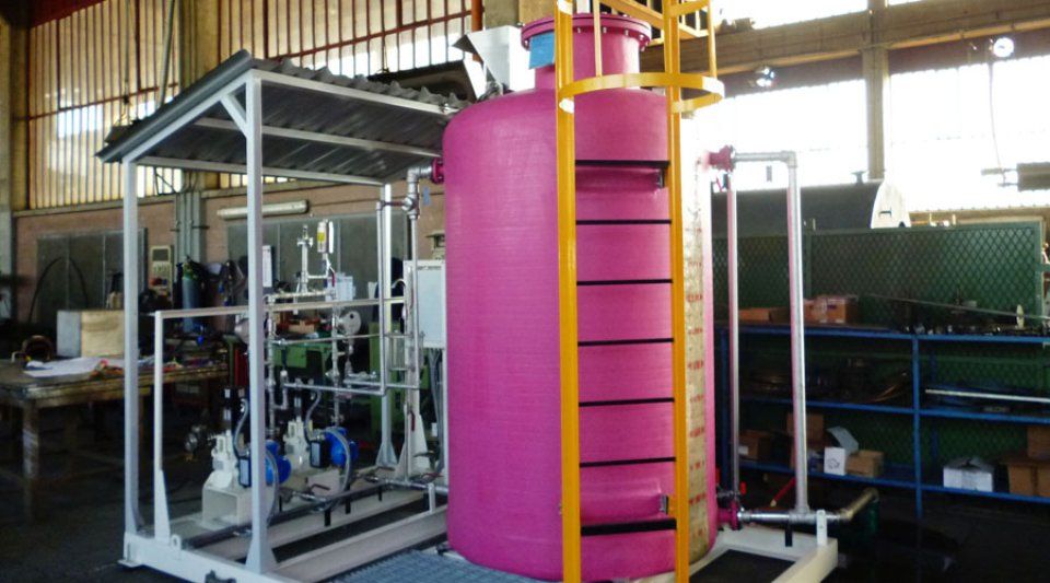
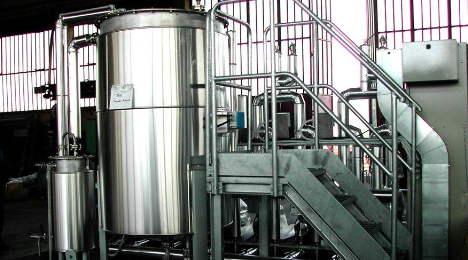
Below is a list of some of the most common systems we make:
- chemical dosing systems
- demineralization systems- Demi
- water treatment systems
- purification systems
- air extraction systems
- fuel thrust and heating system
For more info on our products