


Exchangers
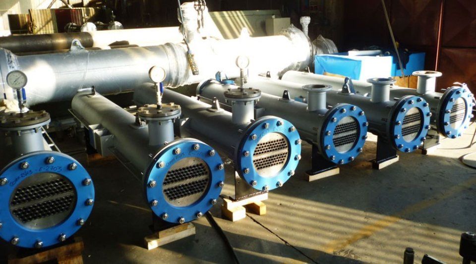
Shell and tube heat exchangers are surface heat exchangers where the currents that are going to be treated have to pass through tubes or pipes that are gathered inside a cylindrical vessel or tank and the space surrounding it (this is also know as the shell).
Compared to normal heat exchangers, the shell and tube heat exchanger is by far the model that is most used, allowing large qualities of heat to be exchanges, with exchange surfaces that can reach tens of thousands of square metres.
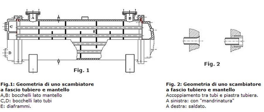
In a shell and tube heat exchanger, the following parts are stand out:
- the end heads (rear head and front head), which define the volume inside the tubes and which is called the "tube side" (represented in blue in the diagram below)
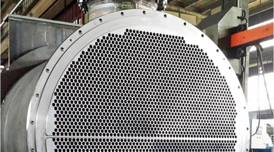
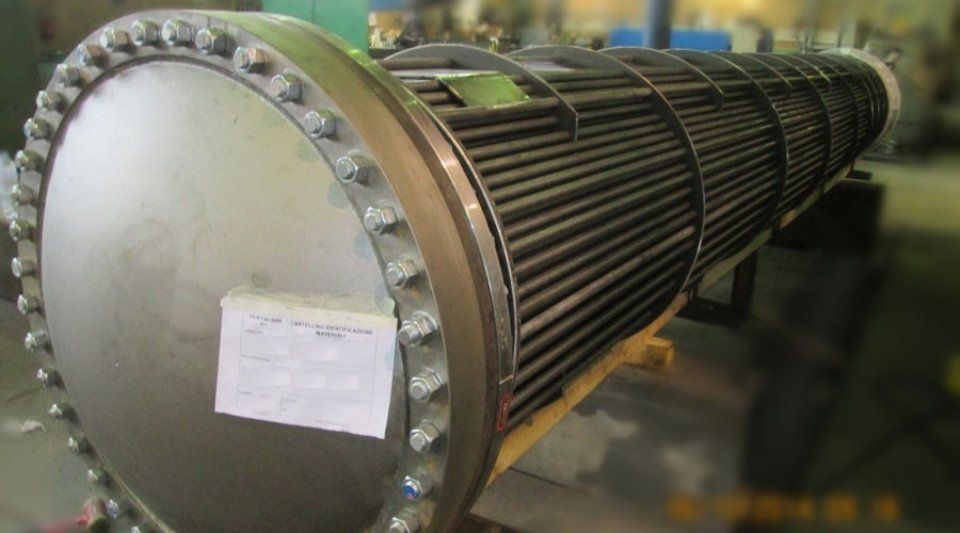
- the tubes themselves which are fixed to a thick perforated sheet called a tube plate. The coupling between the tubes and the tube band can take place by "rolling" and subsequent welding
- the external casing (or shell) defines the external pipe volume and is called "shell side" (represented in red in the diagram below)
The shell is made up of four flanged "nozzles", two reserved for the service fluid (i.e. the cooling / heating fluid used as a vector for heat exchange, generally water) and two reserved for the process fluid (i.e. the fluid that needs to be cooled / heated, which is directly related to the industrial process).
There is a distributor outside the shell, which will only be used with gaseous fluids on the shell side. There may be some transversal sheet metal plates on the shell side, which are also known as baffle plates, and which maintain the flow in a controlled manner within the shell itself.
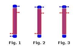
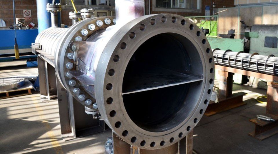
The shell and tube heat exchanger shown in figure 1 is called a single-pass or, more commonly, one-pass, as the fluids enter on both the tube and shell side, and pass through the heat exchanger once and come out. Figure 2 shows a similar heat exchanger, but with two passages on the pipe side or, as they say, a type 2-1 (where 1 stands for 1 step on the shell side). Note, in the upper head, the vertical septum which forces the fluid on the tube side to descend into the tubes and then rise again. There is theoretically no limit to the number of steps; in practice it is rare to find heat exchangers with a number of steps on the tube side greater than 16 and the shell side greater than 4. Figure 3 shows an exchanger 2-2.
Shell and tube heat exchangers are surface heat exchangers where the currents that are going to be treated have to pass through tubes or pipes that are gathered inside a cylindrical vessel or tank and the space surrounding it (this is also know as the shell).
Compared to normal heat exchangers, the shell and tube heat exchanger is by far the model that is most used, allowing large qualities of heat to be exchanges, with exchange surfaces that can reach tens of thousands of square metres.
In a shell and tube heat exchanger, the following parts are stand out:
- the end heads (rear head and front head), which define the volume inside the tubes and which is called the "tube side" (represented in blue in the diagram below)
- the tubes themselves which are fixed to a thick perforated sheet called a tube plate. The coupling between the tubes and the tube band can take place by "rolling" and subsequent welding
- the external casing (or shell) defines the external pipe volume and is called "shell side" (represented in red in the diagram below)
The shell is made up of four flanged "nozzles", two reserved for the service fluid (i.e. the cooling / heating fluid used as a vector for heat exchange, generally water) and two reserved for the process fluid (i.e. the fluid that needs to be cooled / heated, which is directly related to the industrial process).
There is a distributor outside the shell, which will only be used with gaseous fluids on the shell side. There may be some transversal sheet metal plates on the shell side, which are also known as baffle plates, and which maintain the flow in a controlled manner within the shell itself.
The shell and tube heat exchanger shown in figure 1 is called a single-pass or, more commonly, one-pass, as the fluids enter on both the tube and shell side, and pass through the heat exchanger once and come out. Figure 2 shows a similar heat exchanger, but with two passages on the pipe side or, as they say, a type 2-1 (where 1 stands for 1 step on the shell side). Note, in the upper head, the vertical septum which forces the fluid on the tube side to descend into the tubes and then rise again. There is theoretically no limit to the number of steps; in practice it is rare to find heat exchangers with a number of steps on the tube side greater than 16 and the shell side greater than 4. Figure 3 shows an exchanger 2-2.
TEMA Standards
Shell and tube exchangers are the most used, and are also clearly defined by in terms of the standardisation and legislation. In this context, the indications coming from the American TEMA (Tubular Exchanger Manufacturers' Association) apply. The American association publishes an exhaustive collection of standards relating to the classification, sizing and construction of heat exchangers.
The tubes in the heat exchangers do not necessarily have to be straight (we have already spoken about coils, which are incorrect tubes and shells). It is actually more common practice to use U-bend tubes (TEMA U-tube), with variable radii, joined by the tube plate to form U-tubes. These particular models of tube bundle and shell exchangers are called "crowns", and have a single head.
The advantage lies in the fact that the tube can be extracted, and be easily separated from the shell for inspection and cleaning, however this brings less mechanical stability of the tube. The tube itself is being supported by a cantilevered shaft which is subjected to greater stresses and dynamic loads due to vibrations. They are not recommended for corrosive or dirty fluids, as localised pipe erosion can occur along with scaling (or fouling) due to the U-shaped bend.
U-tube heat exchangers can also be used in heating elements inside large equipment, for example in appliances that boil water such as kettles.
The simplest type of shell and tube exchanger is the double tube, which is basically a single tube surrounded by a jacket. As can be seen below.
For more info on our products


